Bộ KIT Học Tập Arduino đáng mua nhất 2023 | Aruino Uno R3
BLK Plus
Tự học Arduino với bộ KIT học tập Arduino UNO R3
https://www.youtube.com/watch?v=rUNlCKcWTPg
Top 10 Dự án Arduino HOT nhất 2023 - Tự học lập trình
Arduino | Top 10 Arduino projects
https://www.youtube.com/watch?v=8cOa-_QiLps
Arduino Uno Rev3 Chính Hãng (Original - Made In Italy)
https://hshop.vn/products/arduino-uno-rev3-chinh-hang-original-made-in-italyMạch Vietduino Uno USB-B (Arduino Uno Compatible)
https://hshop.vn/products/vietduino-uno
Bo mạch Arduino Uno R3 kèm cáp USB
Mạch Arduino Uno R3
Bài 1: Cài đặt Arduino, viết chương trình làm đèn led nhấp
nháy theo yêu cầu | Tự học Arduino cơ bản
Tự học lập trình Arduino Tập 2 | Hướng dẫn cài đặt và sử dụng phần mềm lập trình Arduino IDE
Top 10 arduino projects 2024 | Arduino projects for
beginners | Arduino project
https://www.youtube.com/watch?v=1LVTs1CeHe0
Kythuatvitinh.vn: CẤU TRÚC TESTBOARD
AN INTRODUCTION TO ARDUINO UNO PINOUT
Arduino Uno Pinout Guide
In our last two posts, we focused on the software aspects of the Arduino. We saw that Arduino boards are programmed using a language derived from C and C++ in Arduino's Integrated Development Environment (IDE) and learned a few basic debugging methods. In this post, we'll be taking a closer look at the Arduino hardware, and more specifically, the Arduino Uno pinout. Arduino Uno is based on the ATmega328 by Atmel. The Arduino Uno pinout consists of 14 digital pins, 6 analog inputs, a power jack, USB connection and ICSP header. The versatility of the pinout provides many different options such as driving motors, LEDs, reading sensors and more. In this post, we’ll go over the capabilities of the Arduino Uno pinout.
Arduino Uno Pinout - Diagram
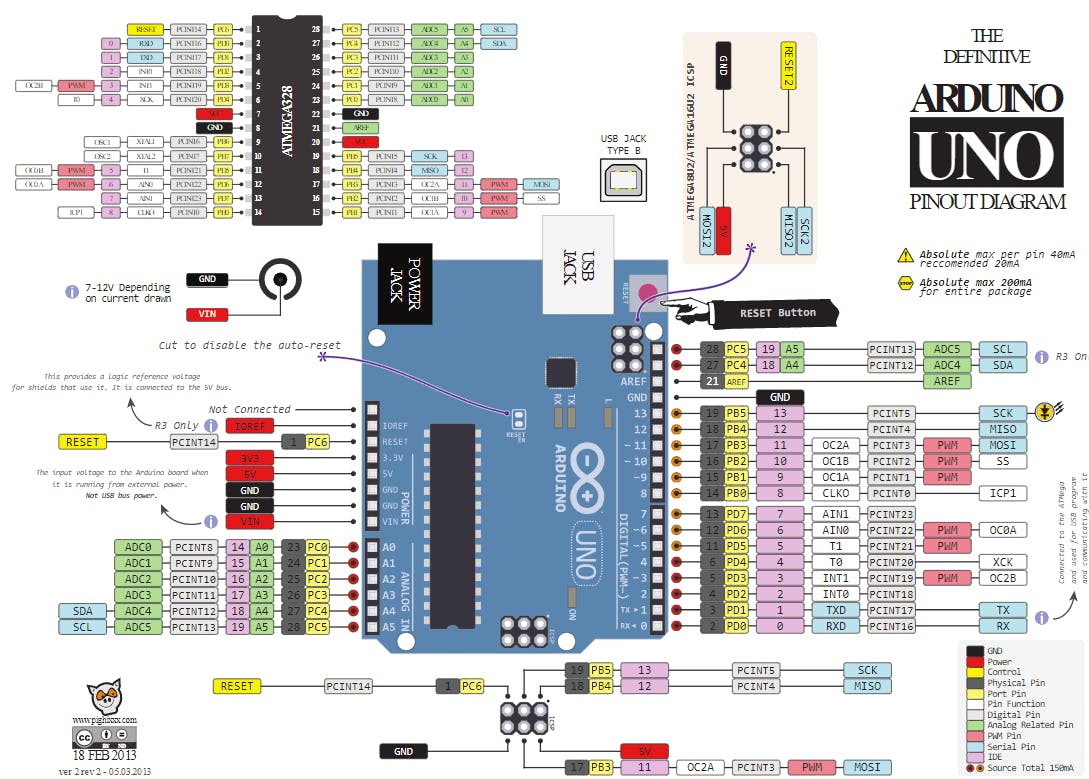
“Pinout of ARDUINO Board and ATMega328PU” by pighixxx is licensed under Creative Commons Attribution-Share Alike 4.0 International
Arduino Uno pinout - Power Supply
There are 3 ways to power the Arduino Uno:
- Barrel Jack - The Barrel jack, or DC Power Jack can be used to power your Arduino board. The barrel jack is usually connected to a wall adapter. The board can be powered by 5-20 volts but the manufacturer recommends to keep it between 7-12 volts. Above 12 volts, the regulators might overheat, and below 7 volts, might not suffice.
- VIN Pin - This pin is used to power the Arduino Uno board using an external power source. The voltage should be within the range mentioned above.
- USB cable - when connected to the computer, provides 5 volts at 500mA.
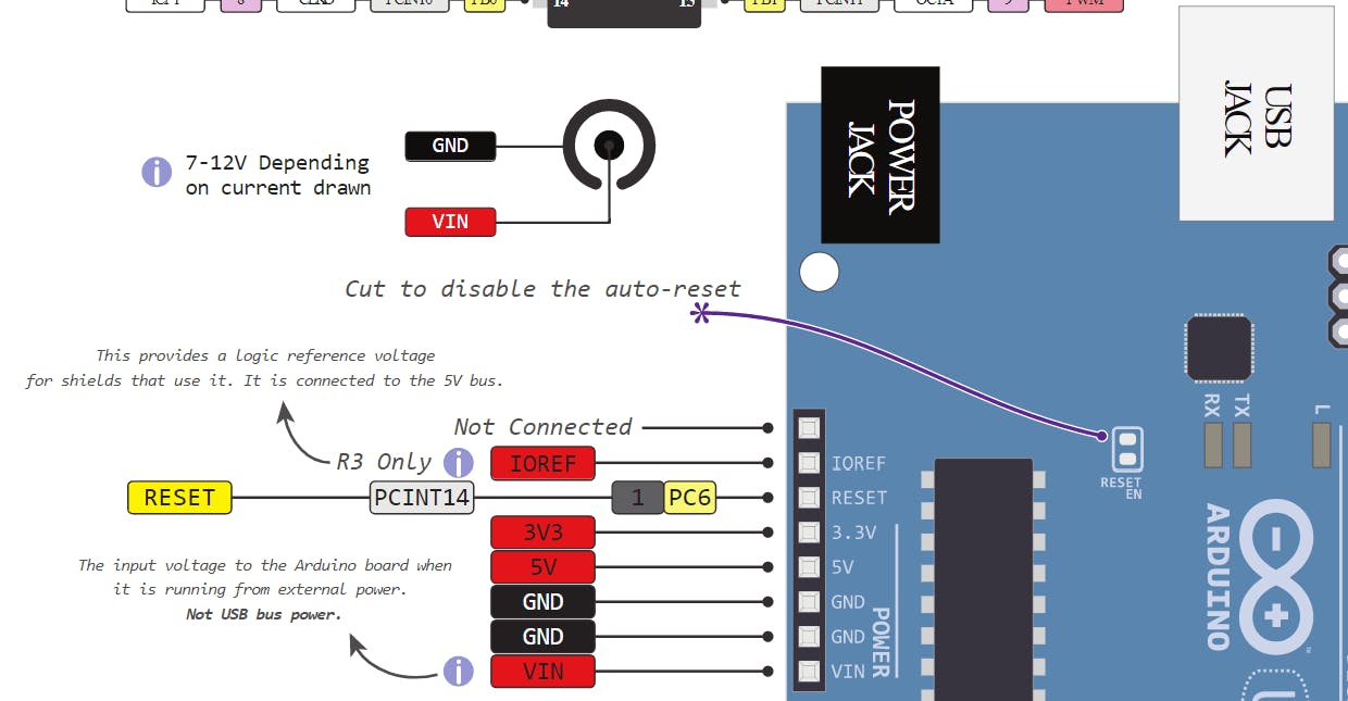
There is a polarity protection diode connecting between the positive of the barrel jack to the VIN pin, rated at 1 Ampere.
The power source you use determines the power you have available for your circuit. For instance, powering the circuit using the USB limits you to 500mA. Take into consideration that this is also used for powering the MCU, its peripherals, the on-board regulators, and the components connected to it. When powering your circuit through the barrel jack or VIN, the maximum capacity available is determined by the 5 and 3.3 volts regulators on-board the Arduino.
- 5v and 3v3
They provide regulated 5 and 3.3v to power external components according to manufacturer specifications.
- GND
In the Arduino Uno pinout, you can find 5 GND pins, which are all interconnected.
The GND pins are used to close the electrical circuit and provide a common logic reference level throughout your circuit. Always make sure that all GNDs (of the Arduino, peripherals and components) are connected to one another and have a common ground.
- RESET - resets the Arduino
- IOREF - This pin is the input/output reference. It provides the voltage reference with which the microcontroller operates.
Arduino Uno Pinout - Analog IN
The Arduino Uno has 6 analog pins, which utilize ADC (Analog to Digital converter).
These pins serve as analog inputs but can also function as digital inputs or digital outputs.

Analog to Digital Conversion
ADC stands for Analog to Digital Converter. ADC is an electronic circuit used to convert analog signals into digital signals. This digital representation of analog signals allows the processor (which is a digital device) to measure the analog signal and use it through its operation.
Arduino Pins A0-A5 are capable of reading analog voltages. On Arduino the ADC has 10-bit resolution, meaning it can represent analog voltage by 1,024 digital levels. The ADC converts voltage into bits which the microprocessor can understand.
One common example of an ADC is Voice over IP (VoIP). Every smartphone has a microphone that converts sound waves (voice) into analog voltage. This goes through the device’s ADC, gets converted into digital data, which is transmitted to the receiving side over the internet.
Arduino Uno Pinout - Digital Pins
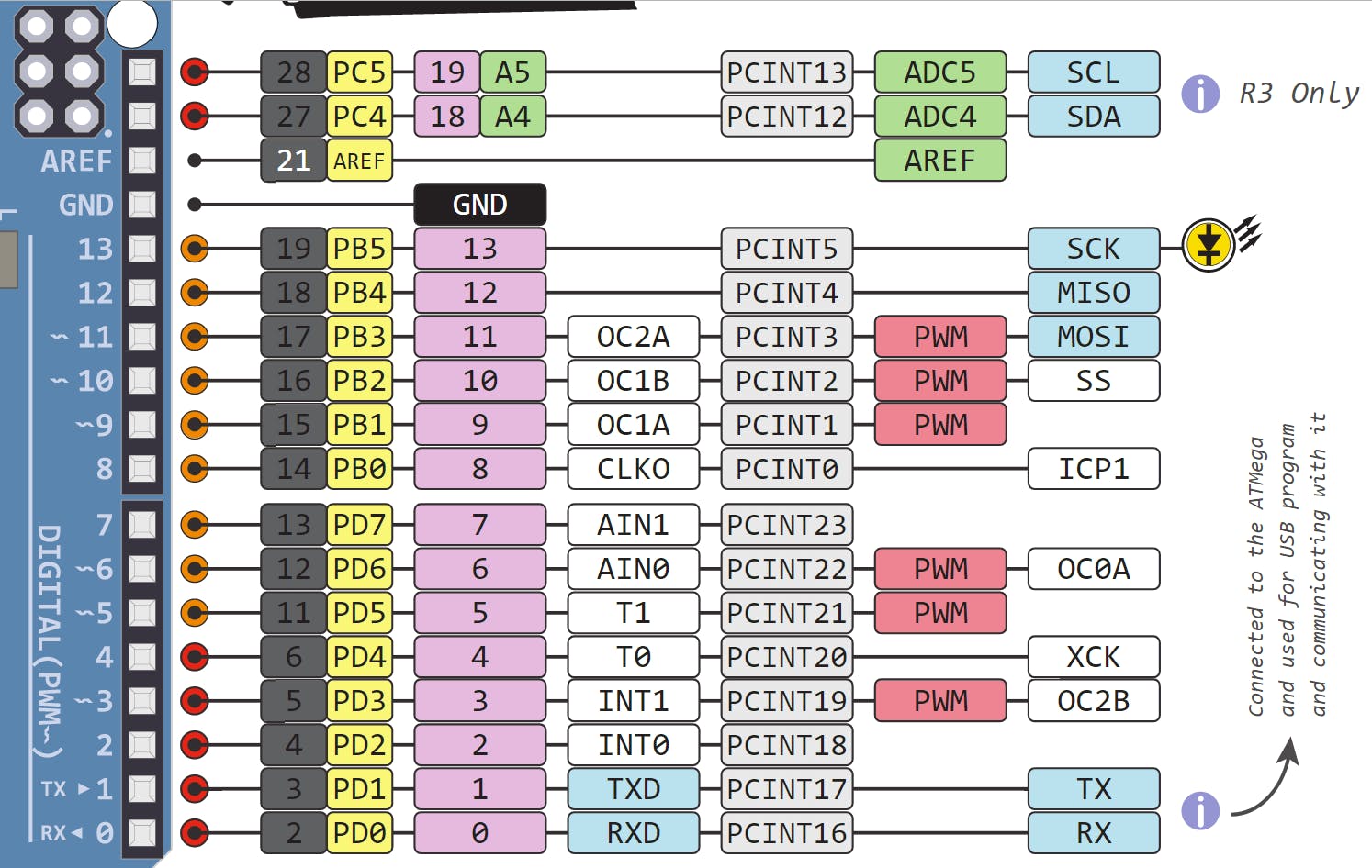
Pins 0-13 of the Arduino Uno serve as digital input/output pins.
Pin 13 of the Arduino Uno is connected to the built-in LED.
In the Arduino Uno - pins 3,5,6,9,10,11 have PWM capability.
It’s important to note that:
● Each pin can provide/sink up to 40 mA max. But the recommended current is 20 mA.
● The absolute max current provided (or sank) from all pins together is 200mA
What does digital mean?
Digital is a way of representing voltage in 1 bit: either 0 or 1. Digital pins on the Arduino are pins designed to be configured as inputs or outputs according to the needs of the user. Digital pins are either on or off. When ON they are in a HIGH voltage state of 5V and when OFF they are in a LOW voltage state of 0V.
On the Arduino, When the digital pins are configured as output, they are set to 0 or 5 volts.
When the digital pins are configured as input, the voltage is supplied from an external device. This voltage can vary between 0-5 volts which is converted into digital representation (0 or 1). To determine this, there are 2 thresholds:
● Below 0.8v - considered as 0.
● Above 2v - considered as 1.
When connecting a component to a digital pin, make sure that the logic levels match. If the voltage is in between the thresholds, the returning value will be undefined.
What is PWM?
In general, Pulse Width Modulation (PWM) is a modulation technique used to encode a message into a pulsing signal. A PWM is comprised of two key components: frequency and duty cycle. The PWM frequency dictates how long it takes to complete a single cycle (period) and how quickly the signal fluctuates from high to low. The duty cycle determines how long a signal stays high out of the total period. Duty cycle is represented in percentage.
In Arduino, the PWM enabled pins produce a constant frequency of ~ 500Hz, while the duty cycle changes according to the parameters set by the user. See the following illustration:
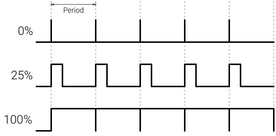
PWM signals are used for speed control of DC motors, dimming LEDs and more.
Communication Protocols
Serial (TTL) - Digital pins 0 and 1 are the serial pins of the Arduino Uno.
They are used by the onboard USB module.
What is Serial Communication?
Serial communication is used to exchange data between the Arduino board and another serial device such as computers, displays, sensors and more. Each Arduino board has at least one serial port. Serial communication occurs on digital pins 0 (RX) and 1 (TX) as well as via USB. Arduino supports serial communication through digital pins with the SoftwareSerial Library as well. This allows the user to connect multiple serial-enabled devices and leave the main serial port available for the USB.
Software serial and hardware serial - Most microcontrollers have hardware designed to communicate with other serial devices. Software serial ports use a pin-change interrupt system to communicate. There is a built-in library for Software Serial communication. Software serial is used by the processor to simulate extra serial ports. The only drawback with software serial is that it requires more processing and cannot support the same high speeds as hardware serial.
SPI - SS/SCK/MISO/MOSI pins are the dedicated pins for SPI communication. They can be found on digital pins 10-13 of the Arduino Uno and on the ICSP headers.
What is SPI?
Serial Peripheral Interface (SPI) is a serial data protocol used by microcontrollers to communicate with one or more external devices in a bus like connection. The SPI can also be used to connect 2 microcontrollers. On the SPI bus, there is always one device that is denoted as a Master device and all the rest as Slaves. In most cases, the microcontroller is the Master device. The SS (Slave Select) pin determines which device the Master is currently communicating with.
SPI enabled devices always have the following pins:
- MISO (Master In Slave Out) - A line for sending data to the Master device
- MOSI (Master Out Slave In) - The Master line for sending data to peripheral devices
- SCK (Serial Clock) - A clock signal generated by the Master device to synchronize data transmission.
I2C - SCL/SDA pins are the dedicated pins for I2C communication. On the Arduino Uno they are found on Analog pins A4 and A5.
What is I2C?
I2C is a communication protocol commonly referred to as the “I2C bus”. The I2C protocol was designed to enable communication between components on a single circuit board. With I2C there are 2 wires referred to as SCL and SDA.
- SCL is the clock line which is designed to synchronize data transfers.
- SDA is the line used to transmit data.
Each device on the I2C bus has a unique address, up to 255 devices can be connected on the same bus.
Aref - Reference voltage for the analog inputs.
Interrupt - INT0 and INT1. Arduino Uno has two external interrupt pins.
External Interrupt - An external interrupt is a system interrupt that occurs when outside interference is present. Interference can come from the user or other hardware devices in the network. Common uses for these interrupts in Arduino are reading the frequency a square wave generated by encoders or waking up the processor upon an external event.
Arduino has two forms of interrupt:
- External
- Pin Change
There are two external interrupt pins on the ATmega168/328 called INT0 and INT1. both INT0 and INT1 are mapped to pins 2 and 3. In contrast, Pin Change interrupts can be activated on any of the pins.
Arduino Uno Pinout - ICSP Header
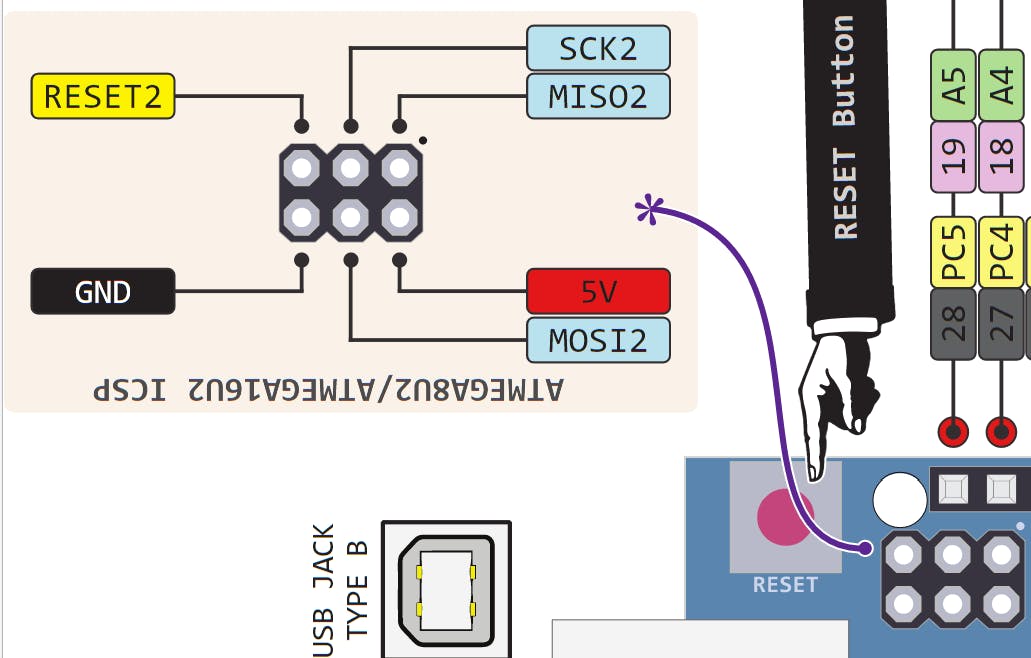
ICSP stands for In-Circuit Serial Programming. The name originated from In-System Programming headers (ISP). Manufacturers like Atmel who work with Arduino have developed their own in-circuit serial programming headers. These pins enable the user to program the Arduino boards’ firmware. There are six ICSP pins available on the Arduino board that can be hooked to a programmer device via a programming cable.
Know your Pinout
The Arduino Uno Microcontroller is one of the most versatile boards on the market today and that’s why we decided to focus on it in this guide. This guide displays most of its capabilities, but there are also more advanced options which we did not go into in this post.
The important thing to know when you choose a board for your project is its capabilities and limitations. It’s also important to understand the different communication protocols that the board uses. Of course, you don’t need to remember all of this information, you can always go back to this post and read the relevant information for you (this is a good time to bookmark this post btw).
If you have any comments or questions, you are welcome to write them below and of course, feel free to share this post with your Arduino-loving friends
=D
Năng lượng
Arduino UNO có thể được cấp nguồn 5V thông qua cổng USB hoặc cấp nguồn ngoài với điện áp khuyên dùng là 7-12V DC và giới hạn là 6-20V. Thường thì cấp nguồn bằng pin vuông 9V là hợp lí nhất nếu bạn không có sẵn nguồn từ cổng USB. Nếu cấp nguồn vượt quá ngưỡng giới hạn trên, bạn sẽ làm hỏng Arduino UNO.
Các chân năng lượng
- GND (Ground): cực âm của nguồn điện cấp cho Arduino UNO. Khi bạn dùng các thiết bị sử dụng những nguồn điện riêng biệt thì những chân này phải được nối với nhau.
- 5V: cấp điện áp 5V đầu ra. Dòng tối đa cho phép ở chân này là 500mA.
- 3.3V: cấp điện áp 3.3V đầu ra. Dòng tối đa cho phép ở chân này là 50mA.
- Vin (Voltage Input): để cấp nguồn ngoài cho Arduino UNO, bạn nối cực dương của nguồn với chân này và cực âm của nguồn với chân GND.
- IOREF: điện áp hoạt động của vi điều khiển trên Arduino UNO có thể được đo ở chân này. Và dĩ nhiên nó luôn là 5V. Mặc dù vậy bạn không được lấy nguồn 5V từ chân này để sử dụng bởi chức năng của nó không phải là cấp nguồn.
- RESET: việc nhấn nút Reset trên board để reset vi điều khiển tương đương với việc chân RESET được nối với GND qua 1 điện trở 10KΩ.
Lưu ý:
- Arduino UNO không có bảo vệ cắm ngược nguồn vào. Do đó bạn phải hết sức cẩn thận, kiểm tra các cực âm – dương của nguồn trước khi cấp cho Arduino UNO. Việc làm chập mạch nguồn vào của Arduino UNO sẽ biến nó thành một miếng nhựa chặn giấy. mình khuyên bạn nên dùng nguồn từ cổng USB nếu có thể.
- Các chân 3.3V và 5V trên Arduino là các chân dùng để cấp nguồn ra cho các thiết bị khác, không phải là các chân cấp nguồn vào. Việc cấp nguồn sai vị trí có thể làm hỏng board. Điều này không được nhà sản xuất khuyến khích.
- Cấp nguồn ngoài không qua cổng USB cho Arduino UNO với điện áp dưới 6V có thể làm hỏng board.
- Cấp điện áp trên 13V vào chân RESET trên board có thể làm hỏng vi điều khiển ATmega328.
- Cường độ dòng điện vào/ra ở tất cả các chân Digital và Analog của Arduino UNO nếu vượt quá 200mA sẽ làm hỏng vi điều khiển.
- Cấp điệp áp trên 5.5V vào các chân Digital hoặc Analog của Arduino UNO sẽ làm hỏng vi điều khiển.
- Cường độ dòng điện qua một chân Digital hoặc Analog bất kì của Arduino UNO vượt quá 40mA sẽ làm hỏng vi điều khiển. Do đó nếu không dùng để truyền nhận dữ liệu, bạn phải mắc một điện trở hạn dòng.
Khi mình nói rằng bạn “có thể làm hỏng”, điều đó có nghĩa là chưa chắc sẽ hỏng ngay bởi các thông số kĩ thuật của linh kiện điện tử luôn có một sự tương đối nhất định. Do đó hãy cứ tuân thủ theo những thông số kĩ thuật của nhà sản xuất nếu bạn không muốn phải mua một board Arduino UNO thứ 2.Khi mình nói rằng bạn “có thể làm hỏng”, điều đó có nghĩa là chưa chắc sẽ hỏng ngay bởi các thông số kĩ thuật của linh kiện điện tử luôn có một sự tương đối nhất định. Do đó hãy cứ tuân thủ theo những thông số kĩ thuật của nhà sản xuất nếu bạn không muốn phải mua một board Arduino UNO thứ 2.
Bộ nhớ
Vi điều khiển Atmega328 tiêu chuẩn cung cấp cho người dùng:
- 32KB bộ nhớ Flash: những đoạn lệnh bạn lập trình sẽ được lưu trữ trong bộ nhớ Flash của vi điều khiển. Thường thì sẽ có khoảng vài KB trong số này sẽ được dùng cho bootloader nhưng đừng lo, bạn hiếm khi nào cần quá 20KB bộ nhớ này đâu.
- 2KB cho SRAM (Static Random Access Memory): giá trị các biến bạn khai báo khi lập trình sẽ lưu ở đây. Bạn khai báo càng nhiều biến thì càng cần nhiều bộ nhớ RAM. Tuy vậy, thực sự thì cũng hiếm khi nào bộ nhớ RAM lại trở thành thứ mà bạn phải bận tâm. Khi mất điện, dữ liệu trên SRAM sẽ bị mất.
- 1KB cho EEPROM (Electrically Eraseble Programmable Read Only Memory): đây giống như một chiếc ổ cứng mini – nơi bạn có thể đọc và ghi dữ liệu của mình vào đây mà không phải lo bị mất khi cúp điện giống như dữ liệu trên SRAM.
Các cổng vào/ra
Arduino UNO có 14 chân digital dùng để đọc hoặc xuất tín hiệu. Chúng chỉ có 2 mức điện áp là 0V và 5V với dòng vào/ra tối đa trên mỗi chân là 40mA. Ở mỗi chân đều có các điện trở pull-up từ được cài đặt ngay trong vi điều khiển ATmega328 (mặc định thì các điện trở này không được kết nối).
Một số chân digital có các chức năng đặc biệt như sau:
- 2 chân Serial: 0 (RX) và 1 (TX): dùng để gửi (transmit – TX) và nhận (receive – RX) dữ liệu TTL Serial. Arduino Uno có thể giao tiếp với thiết bị khác thông qua 2 chân này. Kết nối bluetooth thường thấy nói nôm na chính là kết nối Serial không dây. Nếu không cần giao tiếp Serial, bạn không nên sử dụng 2 chân này nếu không cần thiết
- Chân PWM (~): 3, 5, 6, 9, 10, và 11: cho phép bạn xuất ra xung PWM với độ phân giải 8bit (giá trị từ 0 → 28-1 tương ứng với 0V → 5V) bằng hàm analogWrite(). Nói một cách đơn giản, bạn có thể điều chỉnh được điện áp ra ở chân này từ mức 0V đến 5V thay vì chỉ cố định ở mức 0V và 5V như những chân khác.
- Chân giao tiếp SPI: 10 (SS), 11 (MOSI), 12 (MISO), 13 (SCK). Ngoài các chức năng thông thường, 4 chân này còn dùng để truyền phát dữ liệu bằng giao thức SPI với các thiết bị khác.
- LED 13: trên Arduino UNO có 1 đèn led màu cam (kí hiệu chữ L). Khi bấm nút Reset, bạn sẽ thấy đèn này nhấp nháy để báo hiệu. Nó được nối với chân số 13. Khi chân này được người dùng sử dụng, LED sẽ sáng.
Arduino UNO có 6 chân analog (A0 → A5) cung cấp độ phân giải tín hiệu 10bit (0 → 210-1) để đọc giá trị điện áp trong khoảng 0V → 5V. Với chân AREF trên board, bạn có thể để đưa vào điện áp tham chiếu khi sử dụng các chân analog. Tức là nếu bạn cấp điện áp 2.5V vào chân này thì bạn có thể dùng các chân analog để đo điện áp trong khoảng từ 0V → 2.5V với độ phân giải vẫn là 10bit.
Đặc biệt, Arduino UNO có 2 chân A4 (SDA) và A5 (SCL) hỗ trợ giao tiếp I2C/TWI với các thiết bị khác.


0 Comments
Đăng nhận xét